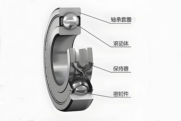
The crankshafts of some small wheeled tractors are supported by two sets of rolling bearings. Rolling bearings consist of an inner ring, an outer ring, rolling elements, and a cage. Both the outer surface of the inner ring and the inner surface of the outer ring feature raceways to enable smooth rolling of the elements. The inner ring is fitted to the crankshaft journal, while the outer ring is fitted to the bearing housing or engine block. Typically, the inner ring rotates synchronously with the shaft, while the outer ring remains stationary. The front and rear main journals of the crankshaft are fixed to the inner rings of the respective rolling bearings. The outer ring of the rear bearing is secured within the engine block bearing housing bore via the rear bearing cap, providing axial positioning. The outer ring of the front bearing is directly mounted in the engine block housing bore without axial fixation, allowing for axial expansion space when the crankshaft expands due to heat.
Failure of the engine crankshaft rolling bearings directly impacts the engine's technical condition, necessitating thorough investigation and resolution of bearing faults. Below are common rolling bearing failures and their root causes:
I. Bearing Ring Play and Fitting Component Wear
1. Outer Ring Play
For ease of installation and removal, the outer ring of the rolling bearing employs a transition fit with the housing bore:
- Front bearing outer ring: Maximum interference fit of 0.035mm, maximum clearance of 0.013mm
- Rear bearing outer ring: Maximum interference fit of 0.016mm, maximum clearance of 0.06mm During assembly, measure the housing bore dimensions to ensure the interference or clearance does not exceed the specified ranges. If exceeded, the housing bore must be repaired.
2. Bearing Inner Ring Movement
The rolling bearing inner ring and shaft neck use an interference fit:
- Front bearing inner diameter: Maximum interference 0.055mm, minimum interference 0.012mm; The rear bearing inner diameter has a maximum interference of
0.046mm and a minimum interference of 0.003mm. Based on these fit parameters, repeated disassembly and reassembly may cause clearance between the inner ring and shaft journal. In such cases, the shaft journal must be repaired before further use.
When bearing-shaft fit loosens, some maintenance personnel attempt to create a tight fit by roughening the shaft surface through embossing or hammering. This practice not only distorts the shaft's geometric shape, causing misalignment during bearing installation, but the roughened areas will eventually flatten, reinstating a loose fit. The correct repair method is: First grind the shaft journal to restore it, then treat the surface using electroplating or spray coating to recover the fit precision.
II. Wear, Deformation, or Breakage of Rolling Bearing Cages
1. Damage Caused by Excessive Assembly Interference
When assembling bearing inner and outer rings, excessive interference can cause the bearing balls to become stuck in the raceway, leading to cage damage during operation. Therefore, precise measurement during assembly is essential to ensure interference meets standard requirements.
2. Failure Due to Inadequate Lubrication
Crankshaft bearings utilize splash lubrication. Insufficient or absent lubricant within the bearing (especially under heavy loads) causes bearing temperature to rise. Typically, the inner ring temperature is approximately 10°C higher than the outer ring. Due to differing thermal expansion rates between the rings, the clearance between balls and raceways disappears, potentially causing cage damage from compression during operation. Therefore, clean lubricant must be applied to the raceways during bearing installation to prevent dry friction caused by insufficient oil splash.
III. Surface Spalling on Rolling Bearing Raceways and Rolling Elements
1. Spalling Caused by Impact Loads and Cyclic Stresses
The rolling elements and raceway surfaces of bearings endure periodic pulsating loads, generating cyclically varying contact stresses. When the number of stress cycles reaches a certain threshold, fatigue spalling may occur on the working surfaces of the rolling elements or raceways. Excessive bearing loads accelerate this fatigue damage. Additionally, improper bearing installation or shaft bending deformation can also cause raceway spalling. Balance weights mounted on engine flywheels and pulleys counterbalance their rotational inertia torque against that generated by rotating engine components. If inertia torque remains unbalanced, severe vibration occurs during engine startup, increasing alternating stress and stress cycle frequency, leading to premature spalling of raceway and rolling element surfaces.
To prevent raceway and rolling element surface spalling, avoid subjecting bearings to additional loads and unnecessary vibrations during operation: control throttle and RPM appropriately during operation to prevent severe tractor shaking; regularly inspect engine mounting bolts to prevent vibration caused by loosening.
2. Foreign Object Ingestion Causing Spalling
When external hard particles (such as metal debris from mating surfaces or bushings, sand grains in lubricating oil, dust, or other contaminants) enter the raceway, they distort its shape. Rolling elements exert maximum pressure at these points, leading to accelerated wear of the raceway and metal spalling. Rolling bearings are high-precision components extremely sensitive to contaminants: During maintenance, use clean, lint-free wipes; never substitute old cotton thread (thread fragments can contaminate lubricant and enter the bearing, causing severe damage). Thoroughly clean shaft journals, housing bores, and bearing inner/outer ring surfaces before assembly to prevent contaminants from entering mating surfaces.
3. Raceway Damage Due to Improper Installation
If pressure is transmitted through the outer ring and balls during installation, pits form at the contact points between the raceway and balls. These pits are the root cause of bearing failure and rapidly expand, leading to flaking and premature bearing failure. Therefore, specialized tools must be used during disassembly and assembly to ensure correct and uniform force application.
IV. Increased Radial and Axial Clearance in Bearings
Beyond excessive dry friction and wear during startup, the primary cause of increased radial and axial clearance is abrasive wear on rolling elements and raceways due to contaminants like metal particles on component surfaces, sand in lubricants, and dust.
Affected by this grinding wear, the clearance between the bearing rings and rolling elements significantly increases. The raceway surfaces become rough and dull, exhibiting uneven scratches. Preventive Measures: Replace lubricating oil on schedule, seal the oil filling holes properly, and strictly prevent contaminants from entering the bearing interior.
Corrosion and Damage of Clutch Release Bearings: Symptoms and Common Causes
Clutch Release Bearing Burnout Symptoms: Similar t…
Operating and Environmental Conditions for Spherical Roller Bearings
Properly determining the installation location, op…
Miniature Bearings — Four Core Application Areas
Miniature bearings are suitable for various indust…
Failure Analysis of Engine Crankshaft Rolling Bearings
The crankshafts of some small wheeled tractors are…
Methods for Removing Bearing Inner and Outer Rings
It is well known that regular maintenance is essen…

Six Steps to Prevent Bearing Failures in Industrial Production
High-performance industrial bearings are critical …